|
 |
|
|
|
Disc Spring Characteristics
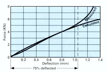
Calculated Characteristic vs Actual Test Results
The example illustrated above is typical of most disc springs, and underlines the necessity of limiting maximum deflection to 75% to avoid sharply increasing force and stress characteristics.
As the compressed disc spring nears its ‘flattened‘ condition, the reducing cone angle results in the movement of bearing point toward the centre, thus effectively shortening the ‘lever‘ length and ‘stiffening‘ the spring.
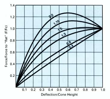
Examples of varying Cone Height / Thickness Ratios
The ability to change the force/deflection characteristic, by way of varying the cone height to thickness ratio, is a particularly useful feature of the disc spring.
Shown above are some examples of different cone height to thickness ratios, and up to a ratio of 1.5 the disc springs may safely be taken to ‘flat‘ or stacked in columns.
Above ratio 1.5 the disc spring will adopt a regressive characteristic, and is capable of ‘push-thro.‘ if not fully supported. Disc springs with cone height/thickness ratios above 2.0 may invert when compressed toward the ‘flat‘ condition.
 |
|
|
 |
|